In order to monitor the engine
performance, we would need to measure the power output and fuel
consumption of the engine.
Before taking the performance one must make sure the following conditions are meet :-
1. Performance must be taken in calm sea never in rough weather.
2. Ship propeller must be fully immersed.
3. Ship is fully laden.
4. Engines load must be kept steady till the performance is taken.
5. Engine running at 85-90% of the MCR.
Readings to be recorded while taking the performance:-
- Fuel oil and lubricating oil(Cylinder oil) flow meter reading, Rpm, revolution and running hour counter must be recorded, first at the starting and other exactly one hour after the first reading in same order first reading were taken.
- Load percentage/ index and governor index.
- Fuel pump index, VIT index, exhaust gas temperature, cooling water outlet temperature, piston outlet lubricating oil temperature of individual cylinder must be recorded.
- Air cooler cooling water inlet and outlet temperature as well as the air inlet and outlet.
- Exhaust gas temperature before T/C and after T/C.
- T/C differential filter pressure.
- Scavenge air pressure before and after air cooler i.e. differential pressure.
- T/C rpm.
- Axial vibration.
- Scavenge air temperature.
- Lubricating oil temperature of main engine inlet and outlet as well the T/C inlet and outlet along with the pressure.
- Fuel oil pressure and temperature.
- Engine room temperature.
- Forward and aft draft of ship.
- Speed of the ship and direction.
- Wind speed and direction.
- Wave height.
- Fuel oil viscosity.
- Test date and test hour.
- Thrust bearing temperature.
- Sea water temperature.
- Position of the ship is also recorded.
Precautions to be taken while taking performance:-
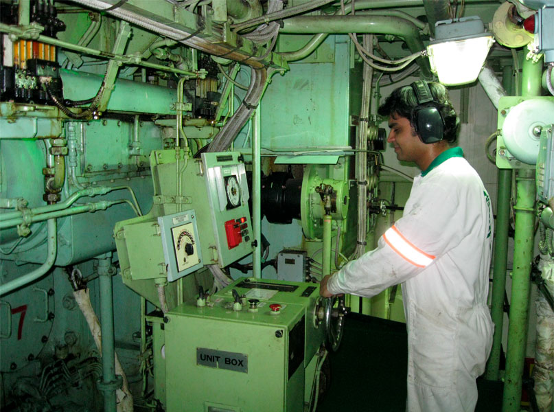
- Take proper PPE protection like gloves, safety shoes etc.
- Indicator cock should be blow through so that it is free of soot and oil.
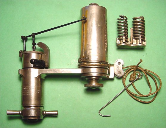
- Indicator card piston should be removed; cylinder and piston should be cleaned and well lubricated. Also the indicator piston tightness in the cylinder must be checked. It can be done by dismantling the piston and allowing it to drop slowly through the cylinder. Bottom of the cylinder is closed and the piston should be held in the position.
- Drum should not hit the stop at the end position. Play in the pencil mechanism will distort the diagram.
- The stylus should be adjusted to a light writing pressure.
- The drum when actuated the motion of the power piston by a cam should be correctly positioned. It represents the travel of the power piston. In that case the compression and expansion diagrams with the fuel cut off should coincide.
Procedure to obtain indicator card:-
- Stretch diagram paper firmly over the drum.
- Before connecting the instrument to the Indicator cock, open indicator cock, allow two or three firing strokes, to blow out soot and combustion residues in the cock.
- Fasten the instrument to the cock so that the cord is taut.
- Take the atmospheric line with the cock shut.
- Open the indicator cock and lightly press the stylus against the paper and make vertical lines as the piston moves up and down, when you are ready to pull the roller string, make sure it is in the bottom and pull the string till the cycle is described.
- Close the cock.
- Disconnect the cord.
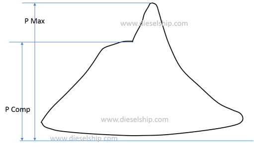
- Make sure that the instrument is not exposed to high temperature for long time. This may affect its accuracy. Remove the hook, turn the drum by hand to a place clear form for the power diagram, take compression pressure line with the fuel cut off.
 |
| Power or In phase card |
 |
| Draw or out of phase card |
| Light Spring card |
 |
| Compression card |
Pic Credit - Dieselship.com
Power calculation
The area can be measured by an instrument
known as ‘Planimeter’ or by the use of the mid ordinates rule. The area
is then divided by the length of the diagram in order to obtain mean height.
This mean height, when multiplied by the spring scale of the indicator
mechanism, gives the indicated mean effective pressure for the cylinder. The
mean effective or average pressure [Pm] can now be used to determine the work
done in the cylinder.
Indicated Power of Unit [ip] =Mean Indicated Pressure [Pm] x Area of Piston [A] x Length of Stroke [L] x Number of Power Strokes per Second [N]
Indicated Power of Unit = Pm L A N
Reference :- Dieselship.com; Authors experience


No comments:
Post a Comment