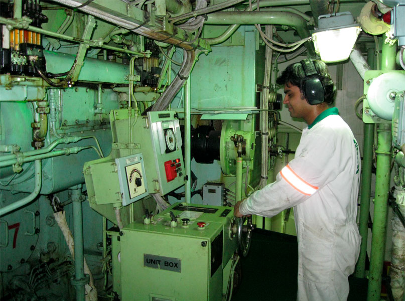
Auxiliary Engine are used on board ship to generate electricity for all the auxiliary equipment in the engine room, navigational equipment, cranes, domestic use like lighting, galley hot plate, etc.
Starting a generator:-
- Direct starting type
- Air motor starting type
Pic credit:- Daihatsu Manual
Ways to start a generator:-
- Local starting- Starting generator from the local station.
- Remote Starting- Remote starting from the control room.
- Auto starting- When one generator fails/trips other generator on auto standby automatically starts and takes the load.
Checks before starting the generator:-
- Check the starting air line.
- Check the lub oil level from the dip stick.
- Check the cooling water valves, F.O. valves and pressure.
- Check F.O. line i.e. H.F.O. inlet to H.F.O. outlet and if D.O. starting then D.O. inlet to D.O. outlet.
- Check for any leakage present.
- Check for turning gear/ turning bar safety switch in the required position i.e. no interlock is active.
- Check the governor oil level.
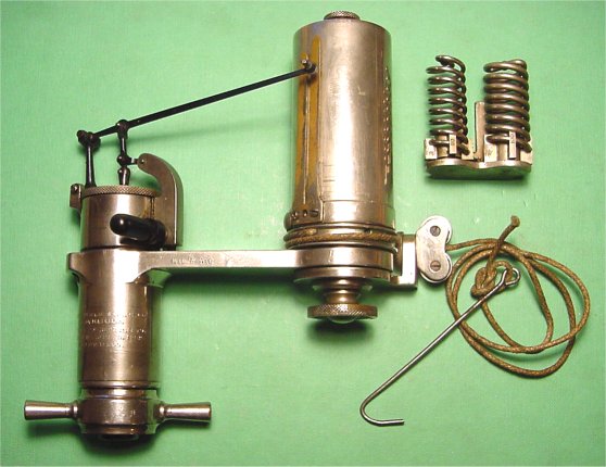
- If indicator valve is present always blow through the engine before starting.
- Engine RPM.
- Abnormal sound.
- Pressure readings.
- Exhaust temperature readings.
- Lub oil level.
- Gas leakage.
- Leakage and loosening of each part.
- Auto mode :- When in auto mode generator automatically comes on load starts sharing the load.
- Manual mode :- When in manual mode first we follow these steps
- Check the generator control is in remote control.
- After that check the voltage of the incoming generator.
- Then switch on the synchroscope.
- Check the movement of the needle/light/pointer moving in clockwise or anticlockwise direction.
- Clockwise direction means running faster i.e. frequency is higher and anticlockwise means running slow i.e. frequency is lower.
- Now Frequency and phase must match so that generators can run in parallel.
- Frequency controller or governor controller is used to control the frequency and thus the when the pointer in the synchroscope moves slowly in clockwise direction and crosses 11 o' clock then breaker is pressed.
- When pointer is moving slowly clockwise direction and reaches 12 o' clock indicates that the incoming generator and the bus voltages are in phase i.e. synchronism.
- Thus generator is on load i.e. running parallel.
- Now they share the load and if load sharing is in "Auto" then generators will share the load equally, if in "Manual" then the load on the generators is set accordingly.
- Always check the parameters during the full operation.
- First put the load sharing in manual mode.
- Transfer the load on the other generator.
- When the KW on the generator which has to removed from load reaches to almost zero but not zero so that reverse power trip is not activated, then generator is offloaded by opening ACB.
- After taking generator off load, generator can be stopped from the ECR by pressing the stop button.
- It must be noted that if before stopping change over is required the fuel must be changed over from H.F.O. to D.O. before off loading. After the complete change over has been done then only the generator must be stopped.
- Take generator in local control.
- Put "Men At Work" sign in the ECR.
- From local panel put lever in stop position.
- Close starting air valve.
- Close fuel oil, cooling water inlet and outlet valves.
- Open the cooling water drain valve to drain the jacket water.
- Open the indicator cock if present.
- Remove all the covers.
- Put the piston in TDC/ Top position.
- Remove all the piping around the cylinder head.
- Remove the F.O. high pressure joint and inlet connector, and extract the fuel injection valve.
- Remove the exhaust manifold mounting bolt.
- Take out the rocker arm device by loosening the mounting nut.
- Extract the valve retainer tee and push rod.
- Using the hydraulic jack(Applied pressure must be according to the "Manufacturer Instruction Manual"), remove the cylinder head mounting nut.
- On the upper surface of the head mount the cylinder head suspending implement. Suspend the head using chain block and wire rope.
- Cover the cylinder liner and intake duct and remove the cylinder head gasket.
- When lowering down the cylinder head care must be taken so that no scratch comes on the lower surface of the cylinder head.
- First remove the parts like inlet and outlet valves, also starting valve, indicator and safety valve if present,
- Inspect the condition of the carbon deposit on the combustion surface, inlet and exhaust port.
- After the inspection, clean the surface and check for corrosion. Also performance color test on surface for cracks.
- Perform the water leak test at specified pressure.
- Inspect the valve guide for corrosion and measure the inner diameter and record the data.
- In case of replacement of the guide:-
- First remove the valve guide with the help of round bar, and strike out the guide with a hammer.
- Fit the new valve guide by means of cold fitting.
- Inspect the valve guide for corrosion and measure the inner diameter and record the data.
- In case of replacement of the guide:-
- First remove the valve by performing the padded welding on the inner surface of the valve seat and quench it with water. Now the seat will contract and will be removed easily.
- Fit the new valve seat by means of cold fitting.
Exhaust valve seat
- Inspect the valve guide for corrosion and measure the inner diameter and record the data.
- In case of replacement of the guide:-
- First remove the valve by performing the padded welding on the inner surface of the valve seat and quench it with water. Now the seat will contract and will be removed easily.
- Fit the new valve seat with new O- Ring by the means of cold fitting.
- For assembly and disassembly special tool is provided by the manufacture.
- After taking out the valves inspect the following:-
- corrosion of valve head area.
- corrosion or bending of valve stem area.
- pitching or blow out of valve seat area.
- contact condition of valve seat and valve stem area.
- crack or corrosion of valve spring, cracks can be found by performing color test.
- Measurement of valve stem
- Measure stem area of inlet and exhaust valve.
- Clearance between the stem area and valve guide.
- Measurement of valve seat and valve head thickness.
- Facing up/ lapping of inlet and exhaust valves.
- Disconnect the circlip and disassemble the parts.
- After washing the parts carefully inspect them and replace if necessary.
- Assemble in the reverse order.
- Disassembly
- Remove the starting valve cover and extract the starting valve assembly from cylinder head.
- Extract the spilt pin, nut and starting valve.
- Remove the starting valve piston and spring.
- Inspection and maintenance
- Clean the individual parts.
- Check the sticking of the starting valve and starting valve piston and the leak of gas from the seat area.
- Corrosion or scratch of the spring.
- Assembly
- Reverse order of disassembly.
- Disassembly
- Loosen the nut and disconnect the rocker arm device assembly.
- Remove the valve retainer tee.
- Remove the snap rings at both the ends of the rocker arm shaft and disconnect the rocker arm and of intake and exhaust valves.
- Inspection and maintenance
- Clean the individual parts.
- Measure the clearance and beyond limit then replace.
- Check the contact conditions of the valve retainer tee and valve retainer guide.
- Check for bend and scratch on the surface.
- Assembly
- Reverse order as of disassembly.
- It should be done in the reverse order of disassembly
- Stop the generator and put the control in local.
- Put Men At work tag.
- Air starting valve closed.
- Indicator cock open. If present.
- Turning gear engaged.
- When the generator is stopped, After some time stop the pre lub pump and let it cool down before the inspection.
- Wear proper PPE and use safety lamps and torches.
- Always prepare the necessary permit and SJA before starting the job and conduct a tool box talk with personal involved in the job.
- First open all the crankcase door and check the gasket for wear.
- Visual inspection of the crankcase walls, crankshaft and lub oil.
- For lub oil its color in important if it is black means blow past in unit.
- Check the smell of the lub oil.
- Test the lub oil in lub oil testing kit.
- Touch the lub oil feel the sludge content, also check the flow of the oil.
- Check the inside of the liner with the help of torch for scoring marks and cracks.
- Inspect the Connecting rod floating.
- Take the main bearing and con rod bearing clearance.
- Check for hot spot on the surface.
- Condition of the crankpin.
- Condition of the main bearing bolt and con rod bolts.
- Check the balancing weight arrangement.
- Check the crankcase relief doors.
- Check for the slip of web.
- check for any signs of wiped bearing.
- Always check for jacket cooling water leakage.
- It varies according to the temperature so it should be taken when the engine is in cold condition.
- Before measurement check the deflection gauge by pushing the contact piece with hand then contact piece and the dial should return to original position correctly.
- For measuring and calculating the deflection always refer the "Manufacturer Instruction Manual".
Check
Roller Path of Cams
- Lub oil low pressure at engine inlet.
- HT jacket cooling water high temperature.
- Overspeed trip.
- Failure of engine speed sensor.
Lambda controller is used to control the excess fuel injection in the combustion chamber of a marine engine when there is a change in the engine load i.e. during a momentary increase in the engine load.
A jet assist system installed on the compressor casing can effectively reduce turbocharger lag. This jet assist system is useful to improve the acceleration performance of the turbocharger. Therefore, the application of a jet assist system in turbocharged engines prevents engine stalls and reduces smoke.
- highly suitable for static, radial and axial dynamic load.
- high speed application.
- Since split type easy to maintain.


