Monday, April 19, 2021

Main Engine Performance

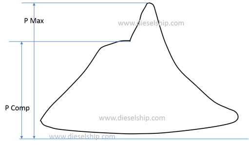
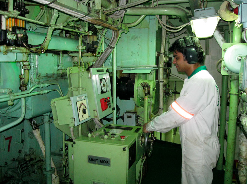
In order to monitor the engine performance, we would need to measure the power output and fuel consumption of the engine. For knowing the performance we have  to  study  the  indicator  cards  along  with  their  draw cards, measure  and  estimate  the  power developed  in  each  unit. Where the  performance  of  scavenge  and  exhausting  are  doubtful,  their  light  spring diagrams  must  also  be  taken  for  investigation. In  those  units  where  compression  is  doubtful  their compression cards  must  also  be  takenData obtained from the performance is then compared with the ship sea trials/machinery trials, shop trials/ test bed trials and the obtained performance curves which enable the engineers to run the ship safely and economically.
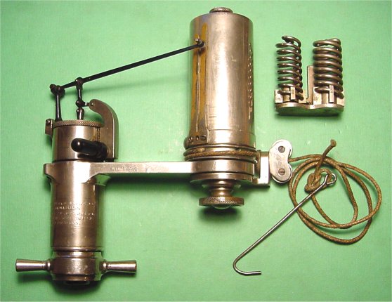


                                                  Pic Credits :- Dieselship.com

Before taking the performance one must make sure the following conditions are meet :-

1.   Performance must be taken in calm sea never in rough weather.

2.   Ship propeller must be fully immersed.

3.   Ship is fully laden.

4.   Engines load must be kept steady till the performance is taken.

5.   Engine running at 85-90% of the MCR.


Readings to be recorded while taking the performance:-

  1. Fuel oil and lubricating oil(Cylinder oil) flow meter reading, Rpm, revolution and running hour counter  must be recorded, first at the starting and other exactly one hour after the first reading in same order first  reading were taken.
  2. Load percentage/ index and governor index.
  3. Fuel pump index, VIT index, exhaust gas temperature, cooling water outlet temperature, piston outlet lubricating oil temperature of individual cylinder must be recorded.
  4. Air cooler cooling water inlet and outlet temperature as well as the air inlet and outlet.
  5. Exhaust gas temperature before T/C and after T/C.
  6. T/C  differential filter pressure.
  7. Scavenge air pressure before and after air cooler i.e. differential pressure.
  8. T/C rpm.
  9. Axial vibration.
  10. Scavenge air temperature.
  11. Lubricating oil temperature of main engine inlet and outlet as well the T/C inlet and outlet along with the pressure.
  12. Fuel oil pressure and temperature.
  13. Engine room temperature.
  14. Forward and aft draft of ship.
  15. Speed of the ship and direction.
  16. Wind speed and direction.
  17. Wave height.
  18. Fuel oil viscosity.
  19. Test date and test hour.
  20. Thrust bearing temperature.
  21. Sea water temperature.
  22. Position of the ship is also recorded.


                                                       Pic Credits- MAN B&W Manual


Precautions to be taken while taking performance:-

  1. Take proper PPE protection like gloves, safety shoes etc.
  2. Indicator cock should be blow through so that it is free of soot and oil.
  3. Indicator card piston should be removed; cylinder and piston should be cleaned and well lubricated. Also the indicator piston tightness in the cylinder must be checked. It can be done by dismantling the piston and allowing it to drop slowly through the cylinder. Bottom of the cylinder is closed and the piston should be held in the position.
  4. Drum should not hit the stop at the end position. Play in the pencil mechanism will distort the diagram.
  5. The stylus should be adjusted to a light writing pressure.
  6. The drum when actuated the motion of the power piston by a cam should be correctly positioned. It represents the travel of the power piston. In that case the compression and expansion diagrams with the fuel cut off should coincide. 

Procedure to obtain indicator card:-

  1. Stretch diagram paper firmly over the drum.
  2. Before connecting the instrument to the Indicator cock, open indicator cock, allow two or three firing strokes, to blow out soot and combustion residues in the cock.
  3. Fasten the instrument to the cock so that the cord is taut.
  4. Take the atmospheric line with the cock shut.
  5. Open the indicator cock and lightly press the stylus against the paper and make vertical lines as the piston moves up and down, when you are ready to pull the roller string, make sure it is in the bottom and pull the string till the cycle is described.
  6. Close the cock.
  7. Disconnect the cord.
  8. Make sure that the instrument is not exposed to high temperature for long time. This may affect its accuracy. Remove the hook, turn the drum by hand to a place clear form for the power diagram, take compression pressure line with the fuel cut off.

After taking indicator cards from all the cylinders, open the instrument and clean all the parts, and lubricate the same.


Types of Indicator Cards

Power or In phase card


Draw or out of phase card


Light Spring card


Compression card

                                                           Pic Credit - Dieselship.com    

Power calculation

The area can be measured by an instrument known as ‘Planimeter’ or by the use of the mid ordinates rule. The area is then divided by the length of the diagram in order to obtain mean height. This mean height, when multiplied by the spring scale of the indicator mechanism, gives the indicated mean effective pressure for the cylinder. The mean effective or average pressure [Pm] can now be used to determine the work done in the cylinder.

Indicated Power of Unit [ip] =Mean Indicated Pressure [Pm] x Area of Piston [A] x Length of Stroke [L] x Number of Power Strokes per Second [N]

Indicated Power of Unit = Pm L A N


Reference :- Dieselship.com;  Authors experience


Saturday, April 17, 2021

FIVA(FUEL INJECTION VALVE ACTUATION)

Solenoid operated proportioning valve and it controls the fuel injection and exhaust valve actuation. Also used on duel fuel marine engine. The new range of engines of 2- stroke marine diesel engines ME-GI, ME/ME-C, ME-B, ME-S executed, with FIVA Valve for regulation of high pressure oil flow for fuel pump and exhaust valve.

In MAN B&W engine FIVA allows the pressurized servo oil under a hydraulic piston. which moves the fuel pump piston upward, raising the fuel pressure and opening the injection valve.

A nitrogen filled accumulator maintains the hydraulic servo oil pressure during operation of the pump.

Working of the FIVA valve


Reference- http://www.marinediesels.info/2_stroke_engine_parts/Other_info/electronic_engine.htm

Reference- http://www.marinediesels.info/2_stroke_engine_parts/Other_info/electronic_engine.htm


Reference of the above 3 pics- https://en.ppt-online.org/322269

Friday, April 16, 2021

Tie Rod

Tie rod holds the three major engine components, "A" frame crankcase and cylinder block or entablature in compression and transmits the firing load to the bed plate.
  • Hydraulically tightened so that the whole engine can be held in compression.
  • Placed as close to the centerline of the crankshaft of the engine to minimize the bending movement in the transverse girder.

Effect of loose or broken tie rod
  • Vibration in the main engine.
  • Fretting of mating surface.
  • Can cause crank shaft misalignment.
  • Bearing damage.
  • Foundation bolts and chocks may get loose.
  • T/C of engine due to vibration in engine which will cause damage to rotor and bearing.

Tie- Rod Breaking reasons:-
  • Not properly tightened.
  • Material and threading of tie rod under rated.
  • Aging of tie rod.
  • Over tightened.
  • Engine overload or peak pressure of cylinder very high.
  • Foundation bolts have become loose or chocks are damaged reading to transmission of vibration in to tie rods.
  • Scavenge fire results in expansion of rods.
  • Quenching screws are loose.
  • Heavy weather can cause engine overload.

Removing a broken tie rod:-
  1. Cut the tie rod out in small pieces.
  2. Passing a wire loop down the tie rod tube to the bottom of the tie bolt and lifting the bolt out.
  3. Jacking the bolt out from below.

Thursday, April 15, 2021

Tilting Pad (Pivoted shoe) Thrust bearing and Lubrication

Each bearing consist of a series of pads supported in a carrier ring, each pad is free to tilt so that it creates a self-sustaining hydrodynamic film.

The carrier ring may be in one piece or in halves with various location arrangements.

Two ways of lubrication in the bearing:

1.  Flooded lubrication

  • Flood the housing with oil, using an orifice on the outlet to regulate the    flow and maintain pressure (Housing pressure- 0.7 to 1.0 bar ) to minimize the leakage.
  • Seal rings are required where shaft passes through the housing.
  • Simple but results in high parasitic power loss due to turbulence at high speed.


                                                        Flooded Lubrication
2. Directed lubrication
  • Where mean sliding speeds in the excess of 50m/s are expected the losses in the flooded lubrication can be eliminated by employing directed lubrication.
  • Reduce power loss by 50%.
  • Reduce the bearing temperature, also reduces the oil flow in most cases.
  • No seal rings are required on the shaft.
  • Oil supply pressure for directed lubrication is 1.4 bar.


                                                     Directed Lubrication
Note:-
  • Directed and flooded bearing have same basic sizes and use identical thrust pads.
  • The bearing housing must be kept free of bulk oil through an  simple drain area around the collar periphery.
  • Oil velocity in the supply passage should not exceed 3m/s to ensure full pressure at the bearing.

Hydraulic thrust metering arrangement
A hydraulic piston is located behind each thrust pad and is connected to a high pressure oil supply. The pressure in the system then gives a measure of the applied thrust load.

Wednesday, April 14, 2021

Slide Fuel Valve

The valve reduces the amount of waste products by eliminating sac volume, as fuel used to drip from the sac on the piston top land.

Valve has NOx reduction potential. 

As per the Kjeld Aabo, Director of Promotion and Customer Support for MAN B&W by changing the number of holes, the spray patterns and spray angle, it reduces the concentration of fuel oil at the injection point which in turn results into lesser peak temperature in the combustion chamber. And by changing the combustion condition the NOx emission changes.


Parts

Consists of valve head, union nut, valve body and nozzle. Within the valve body are non-return valve with a combined slide/valve, thrust spindle with thrust spring, thrust foot and spindle guide.


pic credits: from MAN  B&W manual


Benefits

  • Spray pattern is optimized leading to improved combustion process.
  • Less deposits throughout the gas ways.
  • Reduction in emissions such as HC, NOx and particulate matter.
  • Less visible smoke formation.  
  • Can easily be retrofitted on MC/ MC-C, ME/ME-C.
  • Maintenance is reduced.
  • Simpler testing procedure.
  • Reduced fouling on the piston top land.
  • Improved low load capabilities of the engines.

Main Engine Emergency Maneuvering

All the important machineries on ship are provided with redundancy i.e. backup or standby system. Two similar machines are provided such tha...